Prologue
This project is basically my first foray into hardware reverse engineering. My professor’s at UTSA were the ones who pushed me to branch out into hardware reverse engineering and I am eternally grateful that they did because as time has passed hardware has become my favorite VR target.
The Router
The device I analyzed is a Netis WF2411D model. I had the model from when I was first discovering networking and it was laying in a box for a couple of years until I decided to delve into hardware reverse engineering.
To begin I had to take the board out of its enclosure to allow me to examine it.
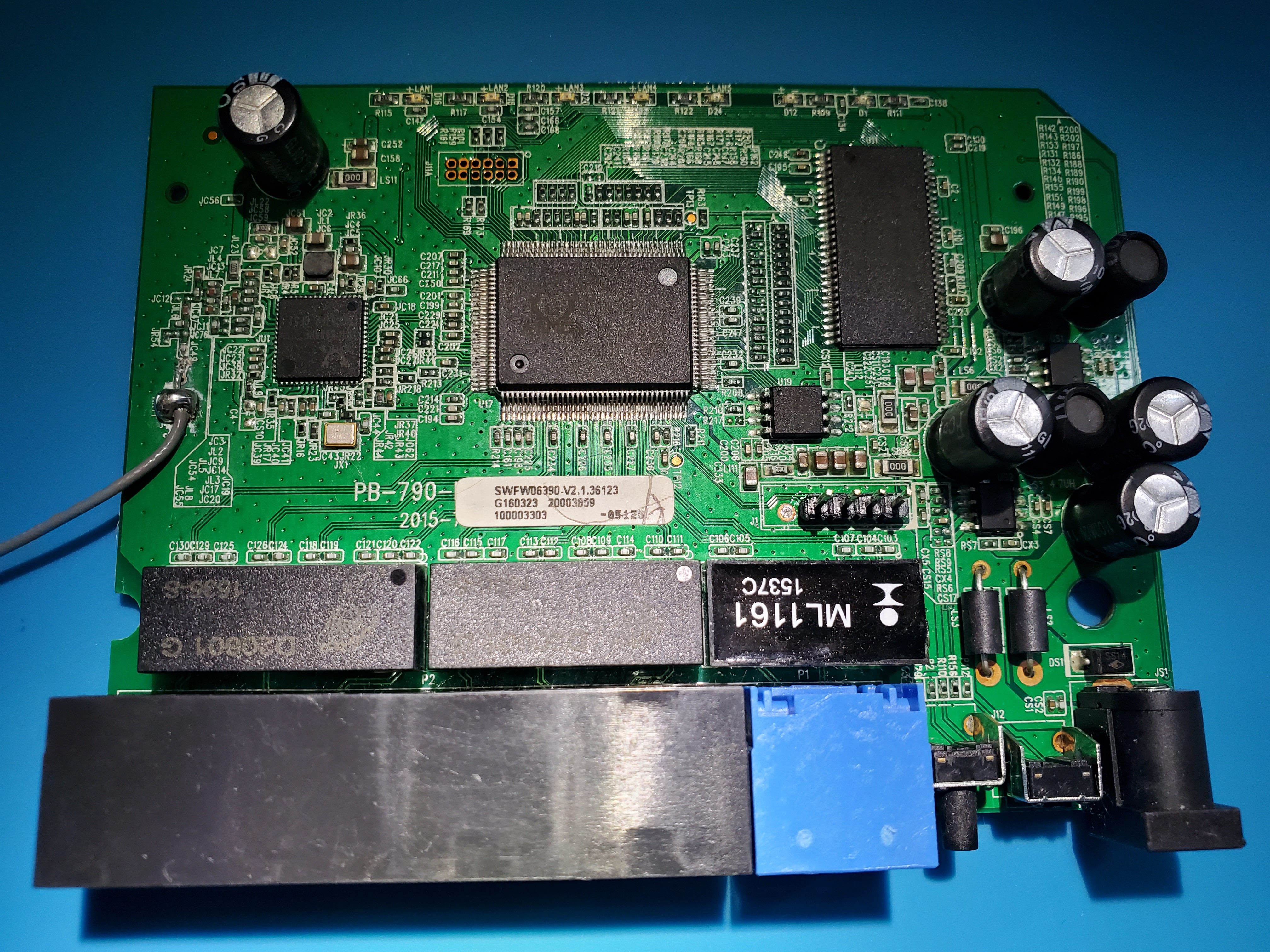
Reconnaissance
After taking the board out of the enclosure I saw that my work was cut out for me because the signature UART contacts were exposed but they had no headers. There was also a flash chip on the board that I was curious of as well.
Soldering
I examined the UART contacts by shining a flashlight underneath the board, this showed the traces that led to each contact. The middle contact clearly had a larger trace connecting to it which indicated to me that this was power (VCC). The two contacts off to the sides of the middle contact had two small traces connected to them which indicated that they were either TX or RX. Finally the outside contacts had no traces connected to them which indicated that they were both ground.
I used a voltmeter to verify the function of the middle contacts.
- The leftmost contact and the rightmost contact had continuity between each other so I assumed that these were each connected to a ground plane.
- The inner leftmost contact was found to be TX as the voltage would often fluctuate from 3.3 Volts to around 2.75 Volts at boot indicating that the device was transmitting.
- The middle contact was confirmed to be VCC or power because it at 3.3v constantly.
- The inner rightmost contact was assumed to be RX as this was the only pin remaining in the UART specification.
After determining the configuration of the pins I cleaned up the lead free solder that came from the factory using an adequate amount of flux, desoldering braid and a hot soldering iron. After cleaning up the board I installed headers so that my logic analyzer could properly make contact with the UART. Admittedly I did botch the first soldering job on this board as I did not have any of the materials listed above. This just goes to show how important it is to have the right tools for the job.
There are three main components to succeed with a soldering job like this.
- Your soldering iron must have sufficient heat for the job, the soldering iron I used for this project was a TS100 because my old analog Velleman VTSS5U soldering iron would not cut it. I soldered at 350 Celsius because more heat is generally better for this type of application. Adding more time can actually cause more harm than good because it can damage the board and the components around the area you are reworking. Also, soldering to and from the ground plane on almost any device like this takes more heat as I had to go up to 420 C to rework these contacts.
- Flux is a very important component for this type of project as it reduces the amount of time it takes for you to take off a component, significantly decreasing the amount of time it takes for you to solder a new component on. It also helps limit the spread of heat to unintended areas which keeps components from getting heat damaged.
- Desoldering Braid makes the process of removing lead free solder much easier because it is several pieces of copper wire that you heat up to entice the existing solder to solder to the braid instead of the contact.
Logic Analysis
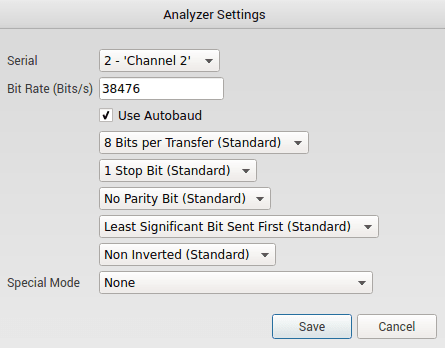
To determine the settings for the UART I used a Saleae 8 channel logic analyzer for simplicity. I attached one channel to the TX pin on the router so that I could determine the baud rate and other settings for connecting to my Bus Pirate as a bridge. I also connected ground to ground to complete the circuit and ran the auto UART analyzer with Saleae’s software.
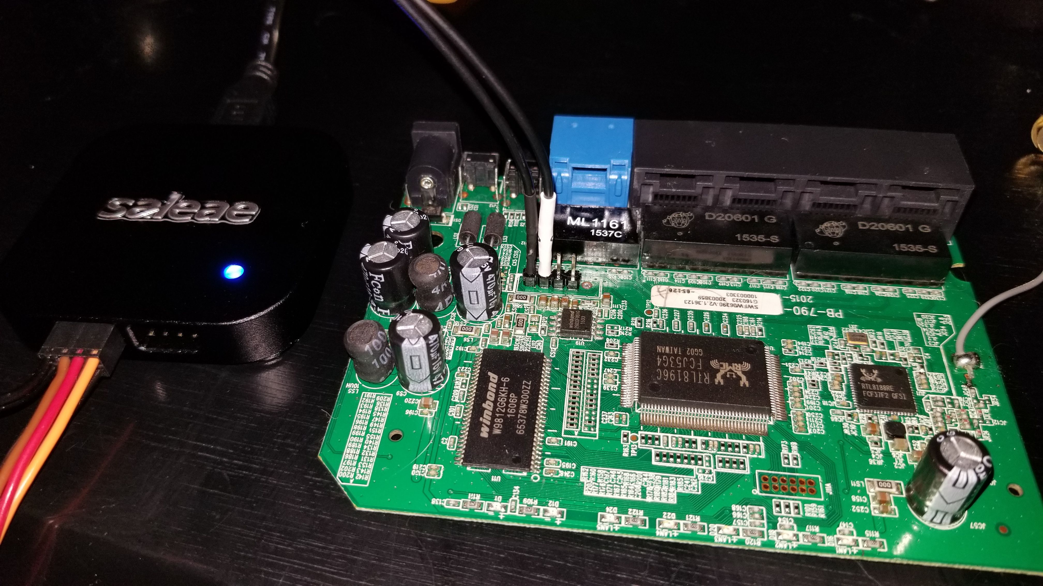
The software yielded a baud rate of 38476 which I rounded to 38400 because it is a standard baud rate on most adapters. It also determined that the settings were 8N1 which is standard for most modern serial interfaces.
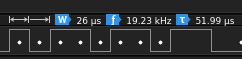
Before moving on I want to make it clear that you don’t need a special Logic Analyzer to determine baud rate as there is an easy formula to calculate it. Below we see that the smallest peak throughout the transmission is 26 micro seconds. If we take that value and put it under one (1/.000026) we get 38461 baud with some change. You can also brute force the settings but that is a tedious process.
UART
After discovering the settings I needed to interface with the UART I connected the device to my Bus Pirate using the standard 10 pin cable included with it while making sure not to connect to 3 Volt to 3 Volt and to connect TX on the router to RX on the Bus Pirate and vice versa.
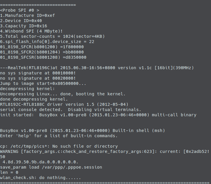
This configuration resulted in a working UART connection with my Bus Pirate which allowed me to watch the Router go through its boot sequence as if it was just a normal computer. This UART connection revealed that system was running Linux and immediately dropped me into a Busybox v1.00-pre8 root shell.
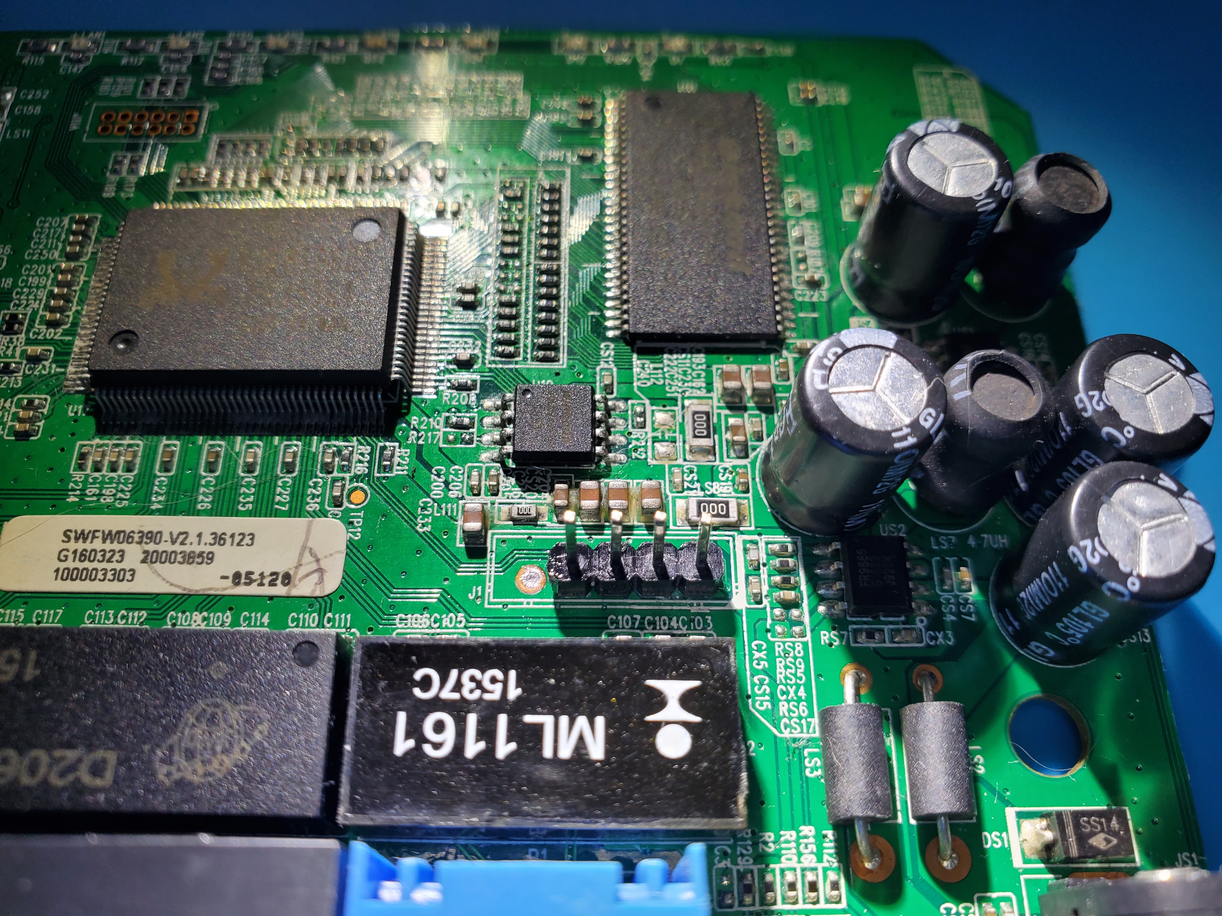
Firmware Dump
After gaining access with the UART I decided to see if I could dump firmware from the onboard flash chip. So I desoldered the chip itself and put it into a soic 8 clip and used a program named FlashRom in conjunction with my Bus Pirate to dump the entire memory of the chip. After briefly analyzing the chip it wasn’t clear what was contained inside the dump as Binwalk showed no known file systems. This post will be updated in the case that I figure out how to deobfuscate the firmware dump but by doing a strings analysis on the dump I did find my SSID and my Password in plaintext.
After analyzing the firmware it appeared that the dump and the files within it were either compressed or otherwise obfuscated. So instead of wasting time trying to understand the dump I decided to look at the firmware over UART where I already had access. I also ended up downloading the firmware from the manufacturer as well to be extra thorough.
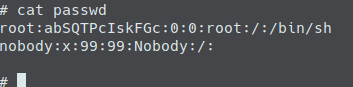
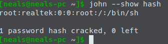
One of the first things I saw when scanning through the various directories was a passwd file with no accompanying shadow file. This piqued my interest so I grabbed the hash and immediately attacked it using John and the rockyou password list just to see if the password was something simple or if it would take a little more effort to crack. The crack was over in a second at the most and it revealed that they had never changed the default password which was “realtek”.
Summary
Although the firmware analysis was short I still very much enjoyed this project as it allowed me to discover the basics of hardware reverse engineering. In the end I found a root shell using the UART pins, the default password for root, the SSID and password for the network and I believe with more research I would be able to find a method to deobfuscate the firmware dump. My plans to go about deobfuscating the dump start with hunting for the addresses referenced in the bootup text from the UART and end with attempting to sniff the data over SPI with the Saleae logic analyzer while it is being loaded at startup.
Finally, big thanks to Saleae for the logic analyzer! It certainly helped me get the UART settings faster than it would have taken without the logic analyzer. I would recommend their logic analyzers as I believe they are simply the best available. If you would like to check out their products you can visit https://www.saleae.com for their full catalog.
Thanks for reading, if you have any feedback don’t hesitate to email me at NealsSec@protonmail.com!